 (http://xv4y NULL.radioclub NULL.asia/2012/12/22/on-parle-du-sdr-cube-dans-monitoring-times/monitoringtimes200/)La revue Monitoring Times (http://www NULL.monitoringtimes NULL.com/) a publié un article court mais flatteur sur le SDR Cube. George N2ABP et Juha OH2NLT sont autorisés à reproduire l’article sur leur site web (http://www NULL.sdr-cube NULL.com/pics/MonitoringTimes NULL.pdf).
Archives de catégorie : Matériel
Matériel radio, transceivers, amplificateurs et montages divers
Prototype balise WSPR à DDS
 (http://xv4y NULL.radioclub NULL.asia/2012/12/21/prototype-balise-wspr-a-dds/100_3339/)Je suis plutôt satisfait de ma semaine! En grappillant quelques heures entre mes occupations professionnelles j’ai réussi à finaliser la mise au point de ma balise WSPR avec un DDS AD9850 (http://xv4y NULL.radioclub NULL.asia/boutique/?slug=product_info NULL.php&products_id=33). Le prototype fonctionne parfaitement et les séquences sont reçues à 100% sur mon ordinateur de contrôle. Les tests sur l’air se sont révélés décevant mais avec moins de 10mW sur 20 mètres, les conditions hivernales et aucune station proche il ne fallait pas non plus rêver. Je vais essayer de bricoler un petit PA d’appoint pour valider les tests.
Un des points sur lequel je bloquais était la quantité de mémoire très restreinte du MSP430G2553. Avec 512 octets on est vite à cours de place pour les variables, d’autant plus que la génération de la séquence de symboles WSPR en consomme plus de 350 à elle seule! Devoir contrôler calculer la séquence WSPR, contrôler le DDS, et l’écran graphique posait pas mal de stress sur le micro-contrôleur. J’ai du réécrire une partie du code et économiser les variables. Les méthodes de programmation moderne nous apprennent à favoriser la lisibilité et la réutilisabilité du code en découpant en fonction ou en créant des classes d’objets. C’est bien beau mais même si les compilateurs modernes optimisent tout cela très bien, cela consomme quand même beaucoup de mémoire. Pas grave sur un micro-ordinateur, mais vite contraignant sur un micro-contrôleur. Les purs et durs programment toujours en assembleur, pour ma part même après 20 ans en ayant débuté à 11 ans sur le microprocesseur 6803 de mon Alice 90 (http://alice NULL.system-cfg NULL.com/) monté à partir de pièces en vrac par F1GUM, la mayonnaise n’a jamais pris…

Si maintenant le code fonctionne parfaitement et que le hardware rempli son rôle, il me reste maintenant à voir comment tout agencer pour en faire un kit facile à reproduire et à monter, et à écrire la documentation! Dernier point technique à valider, l’ajout de 4 boutons pour pouvoir le transformer facilement en VFO ou générateur de signal.
Balise QRSS synchrone avec le LaunchPad/MSP430
 (http://xv4y NULL.radioclub NULL.asia/2012/10/18/balise-wspr-autonome-avec-msp430-le-code-source/kit-wspr-mod-balise/)
[GTranslate]
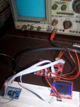
Voici le code que j’ai écrit et qui permet de modifier l‘émetteur original de QRP Labs (http://xv4y NULL.radioclub NULL.asia/2010/08/16/kit-balise-qrss/) pour en faire une balise transmettant régulièrement toutes les minutes paires. Cela est nécessaire si vous voulez que votre transmission soit “superposable” dans les captures du grabber. En effet, de plus en plus d’OM effectuent des compositages de captures sur une base de 10 minutes. En effectuant un traitement de moyenne ou d’interpolation on peut ainsi faire sortir du bruit un signal qui n’était pas visible autrement. Ce traitement est similaire à celui fait en astronomie planétaire avec Lynkeos (http://lynkeos NULL.sourceforge NULL.net/french/index NULL.html) par exemple.
Un kit préparé avec votre indicatif permettant de modifier le circuit de la balise pour fonctionne avec ce programme (ou la version WSPR) est disponible dans la boutique (http://xv4y NULL.radioclub NULL.asia/boutique/?slug=product_info NULL.php&cPath=22&products_id=30).
Ce programme se compile avec Energia (http://energia NULL.nu/) pour un LaunchPad avec MSP430G2553. Il nécessite ma librairie sRTC (http://xv4y NULL.radioclub NULL.asia/2012/12/19/bibliotheque-rtc-pour-energia-version-1-02/).
/* QRSS beacon with 10 minutes frame for MSP430G2553
 * Code for Energia 008

 * By Yannick DEVOS - XV4Y - May-October 2012
    http://xv4y.radioclub.asia/

    Copyright 2012 Yannick DEVOS under GPL 3.0 license
    Any commercial use or inclusion in a kit is subject to author approval

====
 * Ouput on 2 bits PinA and PinB
 * PTT_key output allows to turn on/off the TX PA while sending
 * Mirror on LED1 and LED2 du LaunchPad for testing
 * Output to Serial for testing
 * Using an R-2R ladder it makes the G0UPL/G0XAR beacon frequency shift

====
Revision history :
v1.00    2012-10-26
         First release
v1.01    2012-12-01
         Cleaning and commenting
v1.02    2012-12-19
         Changes to support version 1.02 of RTC library
         Correction for better time accuracy with Serial output enabled

====
This program is free software: you can redistribute it and/or modify
it under the terms of the GNU General Public License as published by
the Free Software Foundation, either version 3 of the License, or
at your option) any later version.

This program is distributed in the hope that it will be useful,
but WITHOUT ANY WARRANTY; without even the implied warranty of
MERCHANTABILITY or FITNESS FOR A PARTICULAR PURPOSE.  See the
GNU General Public License for more details.

You can download a copy of the GNU General Public License at <http://www.gnu.org/licenses/>
*/

// Here under don't touch anything unless you know what you do

#include <legacymsp430.h>
#include <sRTC.h> // Library for RTC clock with MSP430

// Alphabet binary coding by G0UPL
// 0 = dot, 1 = dash
const int _A	=	0b11111001;
const int _B	=	0b11101000;
const int _C	=	0b11101010;
const int _D	=	0b11110100;
const int _E	=	0b11111100;
const int _F	=	0b11100010;
const int _G	=	0b11110110;
const int _H	=	0b11100000;
const int _I	=	0b11111000;
const int _J	=	0b11100111;
const int _K	=	0b11110101;
const int _L	=	0b11100100;
const int _M	=	0b11111011;
const int _N	=	0b11111010;
const int _O	=	0b11110111;
const int _P	=	0b11100110;
const int _Q	=	0b11101101;
const int _R	=	0b11110010;
const int _S	=	0b11110000;
const int _T	=	0b11111101;
const int _U	=	0b11110001;
const int _V	=	0b11100001;
const int _W	=	0b11110011;
const int _X	=	0b11101001;
const int _Y	=	0b11101011;
const int _Z	=	0b11101100;
const int _SPC	=       0b11101111;
const int _0	=	0b11011111;
const int _1	=	0b11001111;
const int _2	=	0b11000111;
const int _3	=	0b11000011;
const int _4	=	0b11000001;
const int _5	=	0b11000000;
const int _6	=	0b11010000;
const int _7	=	0b11011000;
const int _8	=	0b11011100;
const int _9	=	0b11011110;
const int _BRK	 =      0b11010010;
const int _WAIT  =	0b10000000;

byte begin_sec;
int begin_chunk;

// Déclaration et initilisation des variables
byte msgIndex = 1;
byte inc_bit = 8;
byte character = _SPC;
boolean start = false;

byte key = 0;
byte etat = 0;

// *** PARAMETERS
// Here modify to your taste or needs

#define PTT_key 8
#define wsprPinA 10
#define wsprPinB 9
#define LEDPinA 14
#define LEDPinB 2
#define StartBtn 5

const int msg[] = {5, _X, _V, _4, _Y, _WAIT};  // Format, is lenght in decimal and then the character constants including the _WAIT for the end of the sequence

int vitesse = 6;    // Number of seconds per dot (QRSS6 = 6)

// Be carefull, this is only for debugging.
// If you enable this in production, the clock will drift to much (5 seconds in 10 minutes)
#define SERIAL_OUT_INFO

// This is in case you use a MSP430 that does not have Hardwart UART. TimerSerial works great but bring a lot of clock drift. Replace each "Serial" object call in the code by mySerial.
/*
#ifdef SERIAL_OUT_INFO
#include <TimerSerial.h>
TimerSerial mySerial;
#endif
*/

// *** END OF PARAMETERS

#ifdef SERIAL_OUT_INFO
#endif
RealTimeClock myClock;

//******************************************************************
// Defining pins mode
// Encoding the WSPR sequence

void setup() {
  pinMode(PTT_key, OUTPUT);
  pinMode(wsprPinA, OUTPUT);
  pinMode(wsprPinB, OUTPUT);
  pinMode(LEDPinA, OUTPUT);
  pinMode(LEDPinB, OUTPUT);
  pinMode(StartBtn, INPUT_PULLUP);

  myClock.begin();

  #ifdef SERIAL_OUT_INFO
  Serial.begin(9600);
  Serial.println("\n* MSP430 QRSS beacon");
  #endif

  digitalWrite( PTT_key, LOW );
  digitalWrite( wsprPinA, LOW );
  digitalWrite( wsprPinB, LOW );

  digitalWrite( LEDPinA, HIGH );
  digitalWrite( LEDPinB, HIGH );

  #ifdef SERIAL_OUT_INFO
  Serial.println("* Wait clock is set. Sending test sequence.");
  #endif
  begin_chunk = myClock.RTC_chunk;
  begin_sec = myClock.RTC_sec;
  while(digitalRead(StartBtn)) {
    // This is for blinking LED fast
    if ((myClock.RTC_chunk-(begin_chunk+15))%60==0)
      digitalWrite( LEDPinA, HIGH );
    if ((myClock.RTC_chunk-(begin_chunk+30))%60==0)
      digitalWrite( LEDPinB, HIGH );
    if ((myClock.RTC_chunk-(begin_chunk+45))%60==0)
      digitalWrite( LEDPinA, LOW );
    if ((myClock.RTC_chunk-(begin_chunk+60))%60==0)
      digitalWrite( LEDPinB, LOW );

    // We also send a test sequence to help calibrate the transmitter
    if ((myClock.RTC_chunk-(begin_chunk+0))%240==0)
      send_test(begin_sec);

   };
  //randomSeed(myClock.RTC_chunk);
  myClock.Set_Time(0,0,0);
};

//******************************************************************
// Here starts the actual sequence sending

void loop() {
  #ifdef SERIAL_OUT_INFO
  Serial.print("Time:");
  Serial.print(myClock.RTC_min, DEC);
  Serial.print(":");
  Serial.print(myClock.RTC_sec, DEC);
  Serial.print(".");
  Serial.println(myClock.RTC_chunk, DEC);
  #endif

  digitalWrite( PTT_key, LOW );

  digitalWrite( wsprPinB, LOW );
  digitalWrite( LEDPinB, LOW );

  digitalWrite( wsprPinA, LOW );
  digitalWrite( LEDPinA, LOW );

  begin_chunk = myClock.RTC_chunk;

  #ifdef SERIAL_OUT_INFO
  Serial.println("* Waiting 1st sec of every 2 mins.");
  #endif

  while (!(myClock.RTC_sec==1 && (myClock.RTC_min%2)==0)) {  // We start each first second of even minutes
    if ((myClock.RTC_chunk-(begin_chunk+10))%20==0) digitalWrite( LEDPinA, HIGH );
    if ((myClock.RTC_chunk-(begin_chunk+20))%20==0) digitalWrite( LEDPinA, LOW );
  };

  #ifdef SERIAL_OUT_INFO
  Serial.println("\n* Sequence begin");
  #endif
  digitalWrite( PTT_key, HIGH );
  send_sequence();
  #ifdef SERIAL_OUT_INFO
  Serial.println("\n* End");
  #endif
};

//******************************************************************
// Function to send the test sequence
void send_test(char begin_sec) {
    if ((myClock.RTC_sec-(begin_sec+0))%30==0) {
      digitalWrite( PTT_key, LOW );
      digitalWrite( wsprPinA, LOW );
      digitalWrite( wsprPinB, LOW );
      #ifdef SERIAL_OUT_INFO
      Serial.println("* TX Low, Send 00 *");
      #endif
    }

    if ((myClock.RTC_sec-(begin_sec+6))%30==0) {
      digitalWrite( PTT_key, HIGH );
      digitalWrite( wsprPinA, LOW );
      digitalWrite( wsprPinB, LOW );
      #ifdef SERIAL_OUT_INFO
      Serial.println("* TX High, Send 00 *");
      #endif
    }

    if ((myClock.RTC_sec-(begin_sec+12))%30==0) {
      digitalWrite( PTT_key, HIGH );
      digitalWrite( wsprPinA, HIGH );
      digitalWrite( wsprPinB, LOW );
      #ifdef SERIAL_OUT_INFO
      Serial.println("* TX High, Send 01 *");
      #endif
    }

    if ((myClock.RTC_sec-(begin_sec+18))%30==0) {
      digitalWrite( PTT_key, HIGH );
      digitalWrite( wsprPinA, LOW );
      digitalWrite( wsprPinB, HIGH );
      #ifdef SERIAL_OUT_INFO
      Serial.println("* TX High, Send 10 *");
      #endif
    }

    if ((myClock.RTC_sec-(begin_sec+24))%30==0) {
      digitalWrite( PTT_key, HIGH );
      digitalWrite( wsprPinA, HIGH );
      digitalWrite( wsprPinB, HIGH );
      #ifdef SERIAL_OUT_INFO
      Serial.println("* TX High, Send 11 *");
      #endif
    }

};

//******************************************************************
// Function to send the sequence
void send_sequence() {

  while (character != _WAIT) {
    msgIndex = 1;

    while (msgIndex < msg[0]+1) {
      // We read each character in the array
      character = msg[msgIndex];

      inc_bit = 8;

      // Special characters
      if (character == _SPC) {  // For inter-words spacing, we need 5 dots, since we already have 1+2, we need 2 more
         begin_sec = myClock.RTC_sec;
         #ifdef SERIAL_OUT_INFO
         Serial.println("\n* Inter word Space *");
         #endif
         while ( ((60+myClock.RTC_sec-begin_sec)%60)<(2*vitesse) ) {
            delay(0);
         };
         inc_bit = 0;
      };
      if (character == _WAIT) {  // For WAIT or end of sequence, we just skip sending
         #ifdef SERIAL_OUT_INFO
         Serial.println("\n* Enf of sequence *");
         #endif
         inc_bit = 0;
      };

      while (inc_bit) {

        // We read each bit of the character
        etat = bitRead(character,inc_bit-1);

        if (start) {
          if (etat) {
            key=3; // If the bit is 1 then it is a dash
            #ifdef SERIAL_OUT_INFO
            Serial.print("-");
            #endif
          } else {
            key=1; // If the bit is 0 then it is a dot
            #ifdef SERIAL_OUT_INFO
            Serial.print(".");
            #endif
          }

          while (key) {

            digitalWrite( wsprPinB, HIGH );
            digitalWrite( LEDPinB, HIGH );
            digitalWrite( wsprPinA, HIGH );
            digitalWrite( LEDPinA, HIGH );

            // We wait 1 second x VITESSE parameter
            begin_sec = myClock.RTC_sec;
            while ( ((60+myClock.RTC_sec-begin_sec)%60)<(1*vitesse) ) {
              delay(0);
            };

            key--;
          }

          digitalWrite( wsprPinB, LOW );
          digitalWrite( LEDPinB, LOW );
          digitalWrite( wsprPinA, LOW );
          digitalWrite( LEDPinA, LOW );
            // We wait 1 second x VITESSE parameter
          begin_sec = myClock.RTC_sec;
          while ( ((60+myClock.RTC_sec-begin_sec)%60)<(1*vitesse) ) {
            delay(0);
          };
        }

        if (!etat && !start) start=true;

        inc_bit--;

      }
      // We add one space between each characteur (lenght is 3 dots, including the one in the here above loop)
      begin_sec = myClock.RTC_sec;
      #ifdef SERIAL_OUT_INFO
      Serial.print(" ");
      #endif
      while ( ((60+myClock.RTC_sec-begin_sec)%60)<(2*vitesse) ) {
        delay(0);
      };

      start = false;
      msgIndex++;
    };
   };
   character = _SPC;
};

//******************************************************************
// Interruption for the RTC clock
interrupt(TIMER1_A0_VECTOR) Tic_Tac(void) {
  myClock.Inc_chunk();		      // Update chunks
};
Quelques liens utiles pour faire des mesures en HF
 (http://xv4y NULL.radioclub NULL.asia/2012/12/20/quelques-liens-utiles-pour-faire-des-mesures-en-hf/antennapic/)Ayant retrouver le moyen de faire autre chose que des mesures purement indicatives sur mes montages RF, je me retrouve confronté à devoir faire des conversions d’unités, équivalences entre tensions sur une charge et puissances… J’ai sur l’iMac une version de RF Toolbox (http://www NULL.blackcatsystems NULL.com/software/rftoolbox NULL.html) installée depuis longtemps et elle me rend parfois services. Ce même programme existe aussi pour Windows. Le même auteur a aussi développé quelques petits programmes pour iOS et Android (http://www NULL.blackcatsystems NULL.com/iphone/index NULL.html) qui peuvent bien rendre service. Toutefois, bien que RF Toolbox permette de faire très rapidement des calculs d’antennes, de lignes et de filtres, il lui manque certaines conversions simples mais rébarbatives à faire à la main. Cette page web permet quant à elle de faire des changement d’unité HF rapidement (http://www NULL.eeweb NULL.com/toolbox/rf-unit-converter).
De la même façon, en cherchant les valeurs pour me faire une sonde d’oscilloscope (http://xv4y NULL.radioclub NULL.asia/2012/12/12/construire-soi-meme-une-sonde-doscilloscope/) moi-même, je suis tombé sur deux excellents documents écrits par Paul Harden NA5N qui en propose d’autres sur son site (http://www NULL.aoc NULL.nrao NULL.edu/~pharden/hobby/Hobby NULL.shtml). Parmi ces documents vous trouverez ceux sur les ampli classes C, D, E et F (http://xv4y NULL.radioclub NULL.asia/2012/10/22/amplificateur-qrp-en-classe-d-e-et-f/) ainsi que sur les calculs de filtres passe-bas que je vous ai déjà présenté.
Son livre numérique “The Handyman’s guide to oscilloscopes” présente dans la première partie la base des mesures faites avec un oscilloscope et les (http://www NULL.wulfden NULL.org/downloads/tutorials/PaulHardenHandyOscilloscope1 NULL.pdf)réglages (http://www NULL.wulfden NULL.org/downloads/tutorials/PaulHardenHandyOscilloscope1 NULL.pdf) pour y aboutir (ce qu’on doit savoir en sortant du lycée en principe) et dans la deuxième partie des applications plus concrètes aux mesures qu’un radioamateur bricoleur est amené à faire (http://www NULL.wulfden NULL.org/downloads/tutorials/PaulHardenHandyOscilloscope2 NULL.pdf). Soyons clairs, la première partie ne devrait pas présenter de surprise pour aucun d’entre nous. Ca a beau faire un petit moment que j’ai passé l’examen pour la licence, mais cela reste la base des mesures d’électricité. Pour la deuxième partie, si vous êtes comme moi et que vous aviez laissé tombé le fer à souder pendant un moment, il y a parfois des choses qui sont un peu loin dans la brume de nos méninges et le rappels des bases n’est pas mauvais.
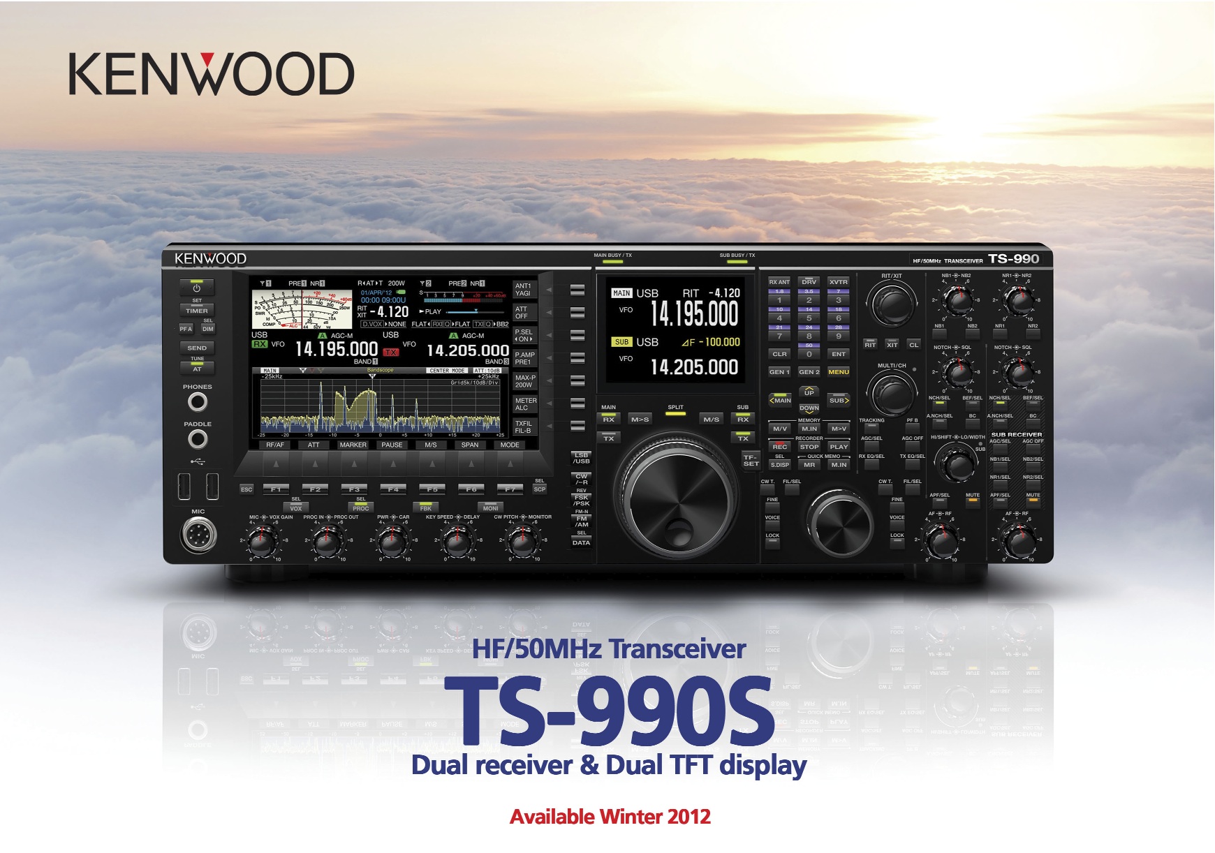
Kenwood Espagne annonce la disponibilité et le prix du TS-990s
 (http://xv4y NULL.radioclub NULL.asia/2012/09/27/plaquette-du-nouveau-kenwood-ts-990s-en-anglais/ts990s_plaquette/)Santos EA4AK souhaitait faire une réservation pour son TS-990s auprès de MercuryBCN le distributeur Kenwood de Barcelone. Il a donc demandé à avoir le plus d’éléments tangibles possibles avant de commander. Jordi, le directeur de ce distributeur lui a rapporté une conversation avec Kenwood Espagne qui confirme les éléments suivants :
- Le prix en Espagne serait de 4999 € Hors Taxes soit un peu plus de 6000 € TTC
- Le nombre d’unités disponibles sera limités dans un premier temps, il faudra donc gérer une liste d’attente
- La date de livraison des premières unités chez le distributeurs serait fin janvier 2013
Petit bémol, Kenwood Espagne ne semble pas avoir la meilleure réputation de sérieux et certains OM émettent des réserves. De plus, il est étonnant qu’aucune autre information sérieuse ne filtre des USA ou du Japon. D’autres sources parlant d’un report possible de plusieurs mois afin de pourvoir livrer des transceivers absent de tous bogues ou défaut. Quand on connaît la complexité d’un tel produit tant du points de vue matériel que logiciel, quelques mois ne semble pas de trop.
Librairie pour piloter un DDS AD9850 avec un LaunchPad/MSP430 ou un Arduino
[GTranslate]
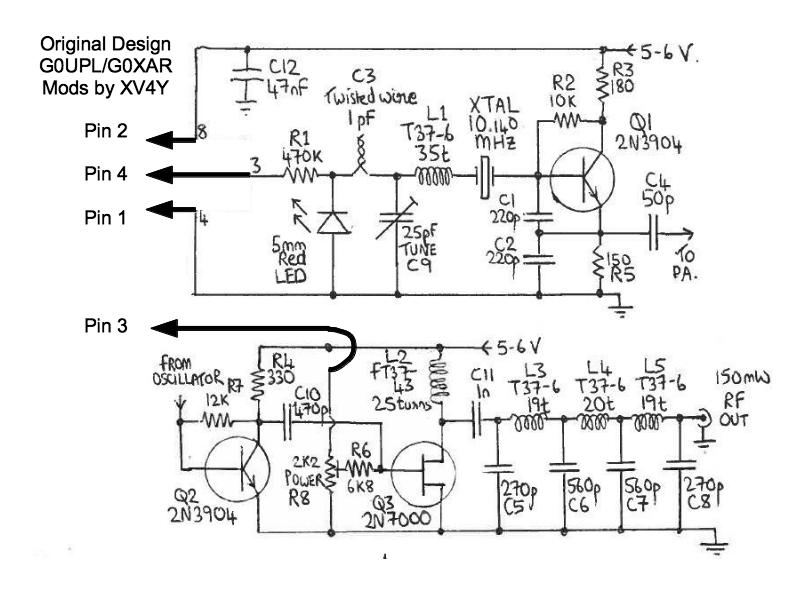
Je partage avec vous un de mes premiers résultats dans la mise au point d’une balise WSPR autonome agile avec générateur de signal à DDS (http://xv4y NULL.radioclub NULL.asia/boutique/?slug=product_info NULL.php&products_id=33). Voici en effet une petite librairie qui simplifiera vos projets pour piloter un DDS de chez Analog Devices comme le AD9850. Vous pouvez aussi facilement concevoir un VFO pour vos montages personnel Bitx (http://xv4y NULL.radioclub NULL.asia/category/ham-radio/materiel/bitx/) ou Bingo.
Cette librairie est assez simple puisqu’elle comporte quelques fonctions pour initialiser le circuit et lui programmer une fréquence. Un paramètre permet de passer le circuit en mode Power Down et de le réveiller au cas où. Cela permet d’économiser de l’énergie et même de faire une forme de CW si votre DDS génère le signal directement.
La communication se fait en mode série via 4 broches d’un micro-contrôleur MSP430G2553 par exemple. Bien entendu il faut aussi fournir l’alimentation et la masse. Fait intéressant, l’AD9850 est très flexible et supporte 3,3V ou 5V pour son alimentation. Comme la librairie est aussi très simple et n’utilise qu’un mode de communication logicielle elle est virtuellement portable sur toutes les familles de micro-contrôleurs. Le code est écrit pour les environnement de développements basés sur Wiring comme par exemple Arduino ou Energia.
Vous pouvez télécharger la librairie complète sur la page de téléchargements (http://xv4y NULL.radioclub NULL.asia/boutique/docs/).
Le code pour le fichier de header AD9850.h
/*
 AD9850.h - Library for adding simple AD9850 control capabilities on MSP430

 Copyright 2012 Yannick DEVOS under GPL 3.0 license
 Any commercial use or inclusion in a kit is subject to author approval

 ====
 Revision history :
 v1.00    2012-12-16
 First release

 ====
 This program is free software: you can redistribute it and/or modify
 it under the terms of the GNU General Public License as published by
 the Free Software Foundation, either version 3 of the License, or
 at your option) any later version.

 This program is distributed in the hope that it will be useful,
 but WITHOUT ANY WARRANTY; without even the implied warranty of
 MERCHANTABILITY or FITNESS FOR A PARTICULAR PURPOSE.  See the
 GNU General Public License for more details.

 You can download a copy of the GNU General Public License at <http://www.gnu.org/licenses/>

 ///////////////////////////////// How to use the lib

 * Create an instance of the object with the pin for CLOCK, LOAD, DATA and RESET

 AD9850 myDDS (P1_5, P2_0, P2_1, P2_2);	 Example for LaunchPad

 * Initialize the AD9850 and do a reset

 myDDS.begin();
 myDDS.reset();

 */

// Core library
#if defined (__AVR_ATmega328P__) || defined(__AVR_ATmega2560__) // Arduino specific
#include "WProgram.h" // #include "Arduino.h" for Arduino 1.0
#elif defined(__32MX320F128H__) || defined(__32MX795F512L__) // chipKIT specific
#include "WProgram.h"
#elif defined(__AVR_ATmega644P__) // Wiring specific
#include "Wiring.h"
#elif defined(__MSP430G2452__) || defined(__MSP430G2553__) || defined(__MSP430G2231__) // LaunchPad specific
#include "Energia.h"
#elif defined(MCU_STM32F103RB) || defined(MCU_STM32F103ZE) || defined(MCU_STM32F103CB) || defined(MCU_STM32F103RE) // Maple specific
#include "WProgram.h"
#endif

// ensure this library description is only included once
#ifndef AD9850_h
#define AD9850_h

// library interface description
class AD9850
{
	// user-accessible "public" interface
public:
	AD9850(uint8_t pinClock, uint8_t pinLoad, uint8_t pinData, uint8_t pinReset);
	void begin();
	void reset();
	void SetFrequency(unsigned long frequency, boolean powerdown);	// Set the frequency and send PowerDown command if needed
	// A few private methods
private:
};

#endif
Le code pour le fichier de déclaration des routines AD9850.cpp
/*
 AD9850.h - Library for adding simple AD9850 control capabilities on MSP430

 Copyright 2012 Yannick DEVOS under GPL 3.0 license
 Any commercial use or inclusion in a kit is subject to author approval

 Based on work by G7UVW

 ====
 Revision history :
 v1.00    2012-12-16
 First release

 ====
 This program is free software: you can redistribute it and/or modify
 it under the terms of the GNU General Public License as published by
 the Free Software Foundation, either version 3 of the License, or
 at your option) any later version.

 This program is distributed in the hope that it will be useful,
 but WITHOUT ANY WARRANTY; without even the implied warranty of
 MERCHANTABILITY or FITNESS FOR A PARTICULAR PURPOSE.  See the
 GNU General Public License for more details.

 You can download a copy of the GNU General Public License at <http://www.gnu.org/licenses/>

 */

// include this library's description file
#include <AD9850.h>
//#include <legacymsp430.h>

#define DDS_CLOCK 125000000

// Constructor /////////////////////////////////////////////////////////////////
uint8_t _DDSpinClock;
uint8_t _DDSpinLoad;
uint8_t _DDSpinData;
uint8_t _DDSpinReset;

AD9850::AD9850(uint8_t pinClock, uint8_t pinLoad, uint8_t pinData, uint8_t pinReset)
{
	_DDSpinClock = pinClock;
	_DDSpinLoad = pinLoad;
	_DDSpinData = pinData;
	_DDSpinReset = pinReset;

};

// Methods /////////////////////////////////////////////////////////////////

void AD9850::begin()
{
    pinMode (_DDSpinClock, OUTPUT);
    pinMode (_DDSpinLoad,  OUTPUT);
    pinMode (_DDSpinData,  OUTPUT);
    pinMode (_DDSpinReset, OUTPUT);

	digitalWrite(_DDSpinReset, LOW);
	digitalWrite(_DDSpinClock, LOW);
	digitalWrite(_DDSpinLoad, LOW);
	digitalWrite(_DDSpinData, LOW);
}

void AD9850::reset()
{
	//reset sequence is:
	// CLOCK & LOAD = LOW
	//  Pulse RESET high for a few uS (use 5 uS here)
	//  Pulse CLOCK high for a few uS (use 5 uS here)
	//  Set DATA to ZERO and pulse LOAD for a few uS (use 5 uS here)

	// data sheet diagrams show only RESET and CLOCK being used to reset the device, but I see no output unless I also
	// toggle the LOAD line here.

    digitalWrite(_DDSpinClock, LOW);
    digitalWrite(_DDSpinLoad, LOW);

	digitalWrite(_DDSpinReset, LOW);
	delay(5);
	digitalWrite(_DDSpinReset, HIGH);  //pulse RESET
	delay(5);
	digitalWrite(_DDSpinReset, LOW);
	delay(5);

	digitalWrite(_DDSpinClock, LOW);
	delay(5);
	digitalWrite(_DDSpinClock, HIGH);  //pulse CLOCK
	delay(5);
	digitalWrite(_DDSpinClock, LOW);
	delay(5);
	digitalWrite(_DDSpinData, LOW);    //make sure DATA pin is LOW

	digitalWrite(_DDSpinLoad, LOW);
	delay(5);
	digitalWrite(_DDSpinLoad, HIGH);  //pulse LOAD
	delay(5);
	digitalWrite(_DDSpinLoad, LOW);
	// Chip is RESET now
}

void AD9850::SetFrequency(unsigned long frequency, boolean powerdown)
{
	unsigned long tuning_word = (frequency * 4294967296 ) / (DDS_CLOCK*10);  // As frequency is in tens of Hertz, we need to multiply by 10
	digitalWrite (_DDSpinLoad, LOW);

	shiftOut(_DDSpinData, _DDSpinClock, LSBFIRST, tuning_word);
	shiftOut(_DDSpinData, _DDSpinClock, LSBFIRST, tuning_word >> 8);
	shiftOut(_DDSpinData, _DDSpinClock, LSBFIRST, tuning_word >> 16);
	shiftOut(_DDSpinData, _DDSpinClock, LSBFIRST, tuning_word >> 24);
	if (powerdown)
		shiftOut(_DDSpinData, _DDSpinClock, LSBFIRST, B00000100);	// If powerdown is true then send PowerDown command
	else
		shiftOut(_DDSpinData, _DDSpinClock, LSBFIRST, 0x0);

	digitalWrite (_DDSpinLoad, HIGH);
}
Nouvelles des kits, balise WSPR à DDS et page téléchargements
Je viens de mettre en ligne une page avec quelques fichiers à télécharger (http://xv4y NULL.radioclub NULL.asia/boutique/docs/) pour le kit SpectroScope audio. Vous y trouverez pour l’instant le manuel utilisateur, les librairies nécessaires à la compilation des sources avec l’environnement Arduino et le code source la mini station météo. J’y ajouterai bientôt les librairies que j’ai écrites pour le MSP430 avec Energia.
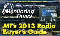
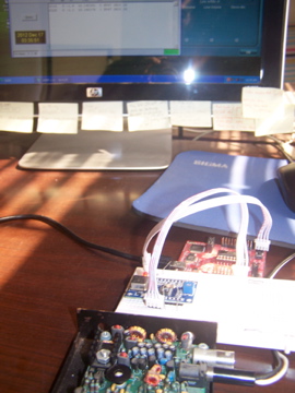
 (http://xv4y NULL.radioclub NULL.asia/2012/12/17/nouvelles-des-kits-balise-wspr-a-dds-et-page-telechargements/100_3338/)A part ça j’ai bien avancé ces derniers jours sur la balise QRSS / WSPR avec DDS 9850. Il reste encore pas mal de travail mais comme vous pouvez le voir j’ai un prototype pleinement fonctionnel sur le banc d’essai. Ce soir il devrait être relié à une antenne mais sans PA les reports risquent d’être limité par les 40mW du DDS. Le kit final comportera un écran graphique, un DDS et des boutons permettant de le reprogrammer comme générateur de signal ou comme VFO au besoin. L’ensemble des composants et logiciels fonctionnent bien mais j’ai du mal à faire cohabiter la génération de la séquence WSPR et le pilotage de l’écran LCD dans les faibles 512 octets de SRAM du MSP430G2553. J’y travaille…
J’ai aussi reçu mon StellarPad mais je ne l’ai pas encore sorti de sa boîte. Chaque chose en son temps. J’avoue ne pas avoir de projet précis qui nécessite toute la puissance d’un tel processeur. Je vais faire quelques en portant des programmes existants mais pour l’instant ce n’est pas une priorité.
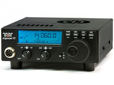
Le Ten-Tec Argonaut VI disponible à la vente
 (http://xv4y NULL.radioclub NULL.asia/2012/12/17/le-ten-tec-argonaut-vi-disponible-a-la-vente/539_web_photo__13009_std/)Merci à K4SWL (http://qrper NULL.com/2012/12/ten-tec-model-539-argonaut-vi-now-available/) pour l’info. Ten-Tec vient de rendre les commandes possible pour son nouveau modèle 539 aussi appelé du nom d’Argonaut VI (http://www NULL.tentec NULL.com/products/Argonaut-VI-QRP-1%252d10-Watt-Transceiver NULL.html). Le prix est de 995 USD aux USA, port non inclus. Pour rappel il s’agit d’un modèle QRP reprenant l’excellent design du modèle 599 Eagle dans un package plus serré et une consommation revue à la baisse.
SDR de Apache-Labs : tous les ANAN-10, ANAN-10 PA et Hermes expédiés
La nouvelle date de fin novembre. Apache-Labs qui produit des SDR de haute performance annonce avoir livré tous les ANAN-10, ANAN-10 PA et Hermes qui lui avait été commandé et payés, soit plus de 200 commandes. Maintenant c’est au tour des ANAN-100 et ANAN-100D de passer en production, le boîtier devant être livré par un fournisseur courant décembre. Les expéditions devraient démarrer début janvier. La petite vidéo ci-dessous montre le fonctionnement d’un des prototypes.
Video ANAN-100 Apache Labs (http://www NULL.youtube NULL.com/watch?v=jXFoJCFwKLM)
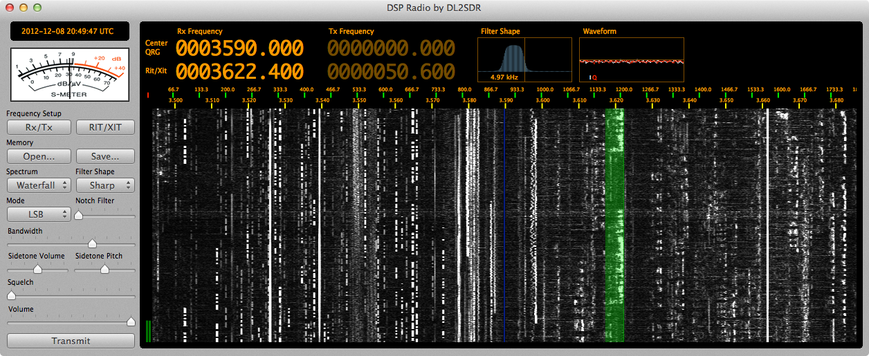
Nouvelle version de DSP Radio pour OS X avec support du FunCube Dongle
 (http://xv4y NULL.radioclub NULL.asia/?attachment_id=2436)J’avoue que je n’utilise plus trop mon SoftRock RXTX, mis à part comme outil pour de la mise au point de circuit HF ou pour quelques séance d’étude de la propagation avec WSPR. Rester devant l’écran d’un micro-ordinateur pour faire le radio ne passionne pas. C’est sympa de “voir” ce que l’on entend sur presque 100 KHz, mais il y a un côté physique qui me manque. Rester dans le noir avec juste le casque sur les oreilles, le manip au bout des doigts et une main sur le vernier pour faire défiler les chiffres du VFO me plaît plus. Chacun ses goûts!
Du coup je n’avais pas vu la mise à jour majeure que Sebastian DL2SDR a apporté à DSP Radio, son logiciel de SDR pour Mac OS X (http://dl2sdr NULL.homepage NULL.t-online NULL.de/). Le principal défaut de ce logiciel c’est l’absence de documentation exhaustive et claire. Sebastian développe seul et pour le plaisir, écrire une doc n’est donc pas sa priorité. Par contre, si vous le contactez par e-mail il répond volontiers aux questions et détaille son code.
DSP Radio utilise le système de gestion du son de Mac OS X ce qui garantit d’excellentes performances, des latences réduites, et une compatibilité avec tous les matériels existants respectants les normes ainsi qu’une ouverture complète au niveau logiciel. L’inconvénient c’est qu’il d’abord se familiariser avec ce dernier, mais le jeu en vaut la chandelle.
Un des apports majeurs de la version 1.3.5 c’est le support du FunCube Dongle (mais pas de la nouvelle version Pro+). Je n’ai malheureusement pas encore eu le temps de la tester car je suis occupé sur d’autres sujets (vous en saurez plus bientôt). J’ai différents logiciels en attente de test et différents articles qui attendent encore un peu de travail avant d’être publiés…